|
AMPLIFIERS,..
(Driving force.)
This is where I will be posting a load of amplifier info, schematics, tweaks and such like
Schematics here are free and offered on the understanding that you do know what you are doing when you
take the case apart, or when you put components together! If it blows up,.. don't blame me, I have
worked with these diagrams and actually FIXED kit. If it still don't work, you have what is known
in my place as a SNAFU! (If it's still smoking after a few seconds,.. it's FUBAR!)
You can always email me and ask for advice,.. provided you have a sense of humour and a thick skin!
I do have some complete service manuals for certain bits of kit. I also know where to get others.
A complete manual is not really downloadable here, quite simply because I have better things to do
than spend days scanning and loading them into the website! If you want one, they are NOT FREE and
will require the provision of a few "drinking vouchers" and "food stamps" to get me off my butt to mail
them to you!
This is the amp just about every guitarist would like good one of.
Bill Jennings, the guy who founded VOX way back,.. came up with this classic.
This schematic is the 1960 version of the VOX AC30. Still a benchmark model!!
 Click the image for a larger version
(or right click and 'save target as'.)
#
For those of you with an old ORANGE MKII, here's the original circuit that came with every head!
Oh yeah,.. if there's some of you thinking you'll try 'cloning' one from other parts than the original
spec components that ORANGE used, DON'T!!. These amps defied logic and actually put out 120watts from
just that 4xEL34 output stage. The transformers were not standard and they were pretty hot running.
When it comes to raw grunt, this was and still is, one heck of a beast in the back-line!
Click on pic for full size.
#
A few years ago, quite a few to some of you reading this, the only transistors we had for power amps were
what are known as 'BIPOLAR' and it didn't take them long to earn the reputation for being a wee bit unreliable.
This is because they don't like running hot, because they get to a certain temperature and then arrive at a point
where they go into 'thermal runaway'. Yes, they just fry themselves even if you do turn down the volume!
Then we got 'MOSFETS'! Oh joy! These newer power transistors have what is called 'negative thermal characteristics',
in other words, when they get hot, they tend to self-regulate their output. That doesn't mean however that they should be
run without any cooling! You still need to run a fan or two into a heatsink! There's a few other things about power
amps that seem to be greatly misunderstood. I've heard very well qualified engineers say that bipolar amps have better
noise and distortion figures,.. which is quite frankly utter crap! The mosfet does not need anything like the same
amount of preamplification, less bits = less noise etc. Also the bipolar transistors need load resistors which, no
matter what you do with them, introduce more distortion and that means also that they need more current to drive them.
More power needed also = more noise and less actual watts output for the power drawn from the mains. In other words, they
ain't so cheap to run.
There's a lot of talk about how good 'CLASS D' amps are because they draw sod all current with no input,.. here we run into
a bit of a grey area. Class D amps have very poor distortion figures at high power but are fine for low power Hi-Fi
but for PA amps, they really ain't as good as a decent mosfet amp. I think there's a lot of rather silly hype about
to try and get us to buy the latest technology. I have here a very slight upgrade to the original HITACHI
application notes for the first breed of mosfets. To be honest, it's still very much the same sort of circuit that
every manufacturer of mosfet amps uses,.. with some minor alterations and extra output devices for higher power outputs.
Plus of course, the transformer would also need to be bigger, or replaced by a modern 'switch-mode' power supply very
similar to those used in a computer.
If you want to add more pairs of output devices, You could also add load resistors in the 'source' of each one to make
sure you don't get one pair doing all the work. 0.2 ohms would do it OK for very little loss, the alternative is to match
each pair AND get all of them matched as close as possible which can get a bit costly. Having said that, Mosfets are pretty
close to matched anyway due to th way they operate and as long as you don't try to drive stupidly low loads, multiple pairs
without matching will still work, which makes a mosfet amp possibly the easiest to build yourself if you want to have a go at it!
(You will still need to know what you are doing with live/exposed circuits,.. it can kill you if you don't The bias has to be set up
to match multiple pairs so if a single pair has a bias of 50 milliamps, each additional pair adds around 25 milliamps.
So if you want to run three pairs at 300 to 450 watts, bias would then be 75 - 100 milliamps. More than three pairs would need
a bit more tweaking of the drive circuits, up-rating the other transistors and such or they will just smoke on you.
Oh yeah, whatever people say about mosfets running hot,.. don't do it! Use a fat heatsink and keep them cool as
possible by blowing it with a fan or two! ALL solid state electronics like to be cool. Only tube stuff likes to be hot enough
to cook dinner on! (I don't suggest you try that, they don't like having stuff spilled in them,.. get very loud and pyrotechnical
all of a sudden.)
The circuit below is rated at 100 watts into 8 ohms and 150 watts into 4 ohms. If the output mosfets are changed for
higher current ones, plus up-rating the supply current from the transformer, they will run into a 2 ohm load at around
220 watts but I haven't ever gone there. Why? Because at very low loads, distortion will be very obvious and the smoothing
capacitors will have their work cut out, even at 10,000uf per rail and they are not cheap caps either!
Oh yeah, toroidal tranformers are not magic, if you want 150 watts out of the amp, the transformer still has losses and the
VA rating will need to allow for those losses,.. 150 watts needs 200VA or it wont cope for long! Anyone tells you different
is taliking crap. Under-rated power supplies are the biggest cause of warranty failures in all kinds of kit!
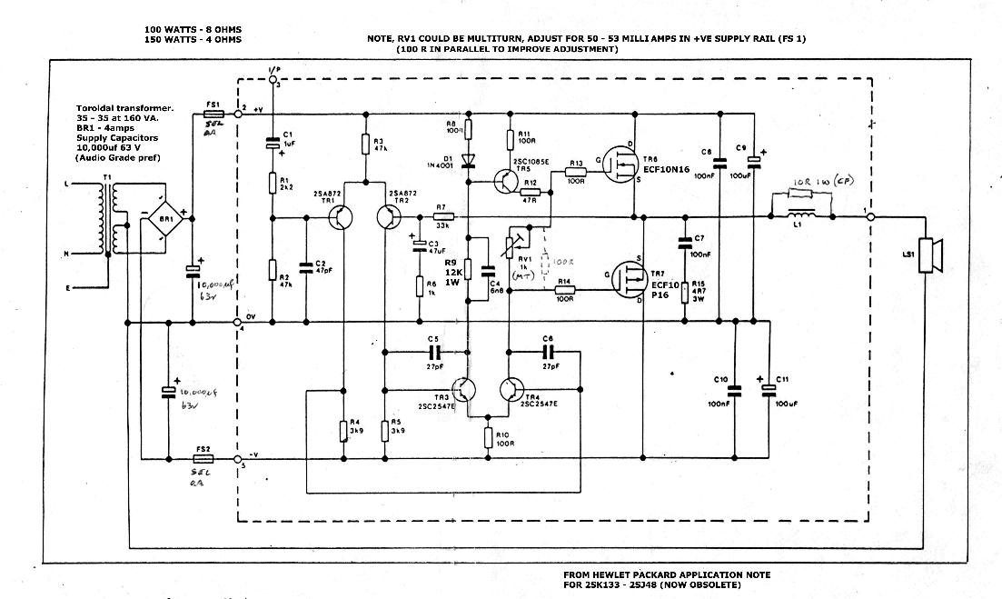
CLICK HERE FOR THE SCHEMATIC
This schematic was the basis of one of the best selling kits that Maplin Electronics ever produced, God only knows
why they decided to drop it, hey I'm not the guy running their company but the number of people who have asked me why
my little amps just keep going, well here's the answer. Simple and straightforward, virtually idiot proof and CHEAP!
I have built literally hundreds of these amps and they just keep working. There are a couple of minor alterations to
the original design which was not perfect. I hear that someone somewhere is still producing these in kit form; if I
find out who it is, I'll post the details here. In the meantime, below is the board layout and track pattern for those who
want to make their own PCBs and build a couple. If you don't know how to do this, I'm not going to go into great detail
here. Go find a friend who does!
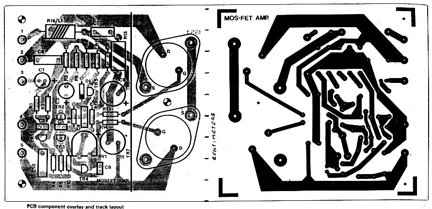
CLICK HERE FOR CIRCUIT BOARD
Meanwhile,.. here's the page from the original layout, soon to be sucked into this one!
 Tech Tips an' Tricks

Help for the wise,.. caution for the not-so-wise!

Template created by: www.caelum.be(unfortunately gone!)
but available from:
WebDesignHelper.co.uk
Modified by: PB
|


 =
=

