ACCESSORY DESIGNS!
(for the skilled or the brave)
This page is where you will find things I have actually built and used. In other words, if you put it together and it's not working,..
you did sommat wrong so check your construction again, dry joints polarity of diodes etc. If you are still not running, try asking me for help!
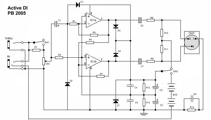
This first one is a really useful transformerless DI BOX. I use this circuit in pairs for stereo guitar effects, keyboards and such
unbalanced outputs. This gives me a useful, balanced, really low-noise signal to the desk, the beauty of balanced being that if that instrument
is feeding back (usually the guitar), then you can invert it on the desk. If you don't know what I'm on about, I think this might be out of your
league!
I don't have the printed board design just yet because it's undergoing some alterations. This one definitely does work well as I have a few on
the PA rig! This design is based on an application from NATIONAL SEMICONDUCTORS AUDIO HANDBOOK and was originally bult around their LM1458 dual
OP-Amp. It's not exactly rocket science and there are several similar ones out there commercially for megga-bucks.
In one form or another it's been round the block with me and many other sound engineers quite a few times.This is version 5 of my original from 1981!
The National Semi books and technical application sheets are really handy and a lot of manufacturers use 'em.
R1 -- 470K
R2 -- 1M
R3,5,7 -- 56K
R4 -- 68K
R8,9 -- 100ohm
R10,11 -- 6K8
R12,13 -- 100K
R14 -- 10ohm
VR1 -- 47K log
C1 -- 10uf
C2,3 -- 220uf 50V
C4,5,8 -- 100nf
C6,7 -- 22uf 50V NP (for "phantom power only" can be polarised (cheaper), positive to R8/9 : remove BVS,SW2)
D1,2,3,4 -- 1N4158
D5 -- 24V 250ma Zener
IC1 -- TLO72
SW1,2 -- SPDT
BVS -- 2x 9Volt NiMH (rechargeable batteries work out much cheaper in the long term!)
(OPTIONAL "power-on" led indicator+1K8 connected across IC1 supply.)
One note on SAFETY if other less techno-geek musos are going to be using your kit! If you do build this with the options
of battery or phantom power,..
DO NOT hook this up to a phantom powered line on batteries (You don't want pyrotechnics).
You could fit a 1N4001 diode between the +ve of the battery and SW2 to make it pretty idiot proof.
SW1 and VR1 select input level. SW1 closed = line / instrument, open = speaker
SW2 selects internal battery supply or remote phantom power. Acts as battery on/off.
Addition of LED-4K7 resistor across zener D5 will give power on/battery OK indicator but drains battery quicker!
IN / THRU for send/return or speaker patch.
OUT balanced via XLR male
The 10 ohm resistor R14 is to prevent earth loops creating hum. Similar resistors can also be used in power amps
rather than removing the earth from the mains plug, a practice often used but not really very safe where you
don't know the state of the wiring in a venue!
(Oh yeah, it was drawn to my attention that the values in this schematic looked a bit odd. To the twat who cracked their
way in and changed them, you do realise that messing round with a project like this could cause serious physical
harm to innocent people. I'm not impressed by your hacking skills,.. get a fekking life!)
© PB 2006